
產(chǎn)品中心
美國強(qiáng)鹿柴油機(jī)維修配件技術(shù)中心
約翰迪爾John Deere柴油機(jī)配件 美國麥克福斯
卡特彼勒柴油發(fā)動機(jī)參數(shù)
沃爾沃發(fā)動機(jī)全系參數(shù)
英國珀金斯原廠配件
珀金斯柴油機(jī)技術(shù)中心
珀金斯發(fā)動機(jī)零件查詢圖冊
日本三菱柴油機(jī)發(fā)電機(jī)配件
德國道依茨 韓國大宇柴油發(fā)動機(jī)配件
康明斯全系列柴油發(fā)動機(jī)
沃爾沃 MTU 原廠配件銷售中心
瑞典沃爾沃遍達(dá)原裝柴油機(jī)配件
康明斯維修技術(shù)中心
卡特彼勒柴油發(fā)動機(jī)原廠配件銷售中心
品牌柴油發(fā)電機(jī)組
康明斯柴油發(fā)動機(jī)配件中心
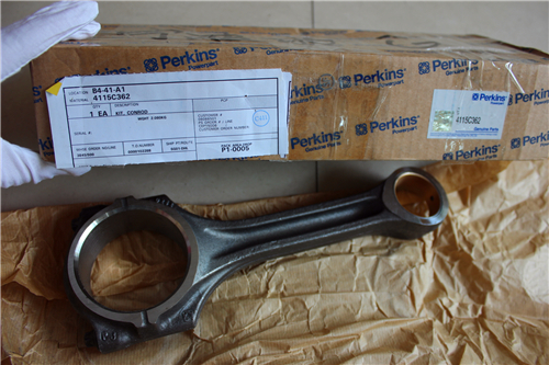
Perkins2306柴油發(fā)動機(jī)配件
詳細(xì)描述
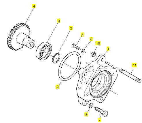
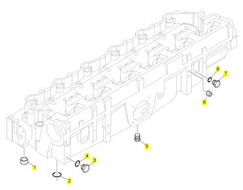
項目 零配件號碼 新件號 描述
CH10567 1 CH10567 螺拴
1 CH10594 1 CH10594 承接器
2 CH10581 1 CH10581 扣環(huán)
3 CH10004 2 CH10004 滾珠軸承
4 CH10592 1 CH10592 燃料噴射泵傳動機(jī)構(gòu)
5 CH10583 3 CH10583 螺拴
5 CH10541 4 CH10255 墊圈
6 CH10593 3 CH10593 墊圈
7 CH10550 3 CH10550 螺拴
8 CH10255 4 CH10255 墊圈
9 CH10590 1 CH10590 密封O型圈
10 CH10798 1 CH10798 螺帽
11 CH12764 1 CH12764 圖釘
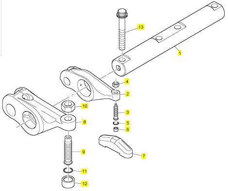
項目 零配件號碼 新件號 描述
1 CH12695 3 CH12695 搖桿軸
1 CH10685 3 CH12695 搖桿軸
2 T400223 12 T400223 搖臂組合
2 CH11165 12 T400223 搖臂組合
3 CH12701 12 CH12701 螺旋
3 CH11162 12 檢查歷史 螺旋
3 CH11916 12 檢查歷史 螺旋
4 T400403 12 T400403 螺帽
4 CH10688 12 T400403 螺帽
4 CH12697 12 T400403 螺帽
5 CH10229 12 CH10229 密封O型圈
6 CH12702 12 CH12702 樞
6 CH10689 12 CH12702 鈕扣
6 CH12510 12 CH12702 樞
7 CH12831 12 CH12831 結(jié)軸塊
7 CH10680 12 CH12831 結(jié)軸
8 T400224 6 T400224 搖臂組合
8 CH11161 6 T400224 搖臂組合
8 CH12698 6 T400224 搖臂組合
9 CH11076 6 CH11076 螺旋
10 CH11077 6 CH11077 螺帽
11 CH11079 6 CH11079 密封O型圈
12 CH11078 6 CH11078 鈕扣
13 CH10566 4 CH10566 螺拴
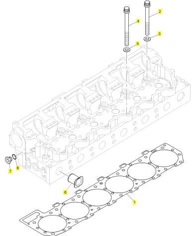
項目 零配件號碼 新件號 描述
1 1 密封墊 - 汽缸蓋
2 CH10712 16 CH10712 螺拴
3 CH10711 16 CH10711 墊圈
4 CH10713 10 CH10713 螺拴
5 CH10711 10 CH10711 墊圈
6 CH10708 6 CH10708 套筒
7 CH10286 3 CH10286 栓塞
8 CH10133 3 CH10133 密封O型圈
項目 零配件號碼 新件號 描述
1 CH10703 24 CH10703 密封墊
2 CH10660 1 CH10660 密封O型圈
3 CH10664 1 CH10664 栓塞
4 CH10119 1 CH10119 密封O型圈
5 CH10262 2 CH10262 栓塞
6 CH10705 1 CH10705 栓塞
7 CH10284 1 CH10284 栓塞
8 CH10133 1 CH10133 密封O型圈
Troubleshooting Section
KENR6224
Illustration 21
Typical engine view
(1) P1 ECM connector
(2) Diagnostic connector
(3) OEM connector
g01285222
B. Thoroughly inspect connectors (1), (2), and (3).
Refer to the Troubleshooting Guide, “Electrical
Connectors - Inspect”.
Illustration 22
P1 terminals that are associated with the Data Link
(P1-8) Data Link +
(P1-9) Data Link −
g01202018
This document has been printed from SPI². Not for Resale
| |||||||||||||
87
Troubleshooting Section
Repair: Repair the connectors and/or the wiring.
Replace parts, if necessary. Ensure that all of the
seals are properly in place and ensure that the
connectors are completely coupled. Verify that the
original fault is eliminated.
STOP.
Test Step 2. Check for a Short Circuit
A. Disconnect the J1 connector.
B. Disconnect the electronic service tool from the
diagnostic connector.
C. Measure the resistance between the points that
are lis ted in Table 13. Be sure to wiggle the wires
in the harnesses as y ou make each resistance
measurement.
Table 13
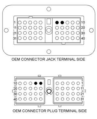
Illustration 23
g01285663
OEM connector terminals that are associated with the Data Link
(6) Data Link −
(7) Data Link +
C. Perform a 45 N (10 lb) pull test on each of the
wires that are associated with the Data Link.
D. Check the allen head screw on each ECM
connector for the proper torque. Also, check the
allen head screw on the customer connec tor for
the proper torque. Refer to the Troubleshooting
Guide, “Electrical Connectors - Inspect” for the
correct torque values.
Expected Result:
All connectors, pins, and soc kets are completely
inserted and coupled. The harness and wiring are
free of corrosion, of abrasion, and of pinch points.
Results:
• OK – The harness and the connectors appear to
be OK. Proceed to Test Step 2.
• Not OK – The connectors and/or the wiring are
not OK.
Expected Result:
Each check of the resistance indicates an open
circuit.
Results:
• OK – Each check of the resistance indicates an
open circuit. Proceed to Test Step 3.
• Not OK – At least one check of the resistance
does not indicate an open circuit. There is a short
circuit in the harness or in a connector.
Repair: Repair the connectors and/or the wiring.
Replace parts, if necessary. Verify that the original
fault is eliminated.
STOP.
Test Step 3. Check for an Open Circuit
A. Fabricate a jumper wire. Use the jumper wire in
order to create a short circuit in the diagnostic
connector between terminals J63-D (Data Link +)
and J 63-E (Data Link −).
B. Measure the resistance between P1-8 (Data Link
+) and P1-9 (Data Link −).
This document has been printed from SPI². Not for Resale
![]() 88
88
Troubleshooting Section
KENR6224
Expected Result:
Check that each of the resis tances is less than ten
Ohms.
Results:
•
•
0253-02 Personality Module erratic, intermittent
or incorrect
0268-02 Programmable Parameters erratic,
intermittent or incorrect
Test
Step 1. Inspect the
Electrical
•
OK
– Each of the resistances is less than ten
Connectors and the Wiring
•
Ohms.
Repair: Perform the following procedure:
1. Connect the J1/P1 connectors. Connect
the electronic service tool to the diagnostic
connector.
2. Check the Data Link for proper operation. If the
Data Link does not operate correctly, there may
be a fault in the ECM.
Temporarily install a new ECM. Check the Data
Link again. If the new ECM eliminates the fault,
ins tall the original ECM and verify that the
original fault returns. If the new ECM operates
correc tly and the original ECM does not operate
correctly, replace the original ECM. Verify that
the fault is eliminated.
STOP.
Not OK – At least one check of the resistance is
greater than ten Ohms. There is an open circuit or
excessive resistance in the harness. There may
be a fault in a connector.
Repair: Repair the wiring and/or the connectors.
Replac e parts, if necessary. Verify that the original
fault is eliminated.
STOP.
i02568143
|
Illustration 24
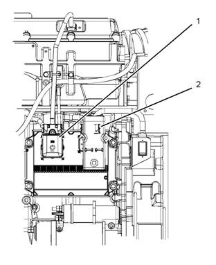
ECM connectors
(1) J2/P2 connectors
(2) J1/P1 connectors
B. Thoroughly inspect connectors (1) and (2).
ECM Memory
- Test
Inspect the battery connections. Refer to the
Troubleshooting Guide, “Electrical Connectors
- Inspect”.
System Operation Description:
The Electronic Control Module (ECM) is the computer
that controls the engine. The flash file contains the
software that controls the operation of the ECM.
The flash file is the instructions that are used by the
ECM to control the engine. For this reason, updating
the flash file to a different version may affect some
engine functions.
This procedure covers the following diagnostic codes :
C. Check the allen head screw on each ECM
connector for the proper torque. Refer to the
Troubleshooting Guide, “Electrical Connectors
- Inspect”.
D. Check the harnesses and the wiring for abrasion
and for pinch points.
Expected Result:
All connectors, pins and sockets are completely
coupled and/or inserted and the harnesses and wiring
are free of corrosion, of abrasion or of pinch points.
This document has been printed from SPI². Not for Resale
![]() KENR6224
KENR6224
89
Troubleshooting Section
Results:
• OK – The harnesses and the connectors appear
to be OK. Proceed to Test Step 2.
• Not OK – The wiring and/or a connector are not
OK.
Repair: Repair the wiring and/or the connectors.
Replac e parts, if necessary. Ensure that all of the
seals are properly in place and ensure that the
connectors are completely coupled.
Verify that the repair eliminates the fault.
•
Acquire factory passwords. Clear the 253-02
diagnostic code. Return the engine to service.
STOP.
Not OK – The correct flash file is not installed in
the ECM.
Repair: Program the correct flash file into the
ECM. Refer to the Troubleshooting Guide, “Flash
Programming”. Verify that the fault is eliminated.
STOP.
|
Test Step 2. Check For Diagnostic Codes
A. Connect the elec tronic service tool to the
diagnostic connector. Refer to the Troubleshooting
Guide, “Electronic Service Tools”.
B. Restore the electrical power to the ECM.
C. Observe the “Active Diagnostic” screen on the
electronic service tool. Wait at least 30 seconds
so that any codes may become active. Look for
these codes:
• 253-02
• 268-02
Expected Result:
The 253-02 or 268-02 codes are not ac tive.
Results:
• Active 253-02 code – Diagnostic code 253-02 is
active. Proceed to Test Step 3.
• Active 268-02 code – Diagnostic code 268-02 is
active. Proceed to Test Step 4.
the Flash File
A. Verify that the flash file agrees with the original
engine arrangement.
Expected Result:
The c orrect flash file is ins talled in the ECM.
Results:
• OK – The correct flash file is installed in the ECM.
Repair: The engine will not start until the 253-02
diagnostic code is cleared. Clearing this code
requires factory passwords.
|
A. Verify that the configuration parameters are
correc t for the engine application. Refer to the
Troubleshooting Guide, “System Configuration
Parameters ”.
B. Verify that the injec tor trim files are correct for the
engine application. Refer to the Troubleshooting
Guide, “Injector Trim File”.
Expected Result:
The configuration parameters and the injector trim
files are correct.
Results:
• OK – The c onfiguration parameters and the
injector trim files are correct.
Repair: Clear the diagnostic code and return the
engine to service.
STOP.
• Not OK – The configuration parameters and/or the
injector trim files are not correct.
Repair: The 268-02 diagnostic code cannot be
cleared until all of the parameters and/or all of the
injector trim files are programmed with the correct
values. The engine may use a default torque map
or the ECM may limit the engine to low idle until
this diagnostic code is cleared.
Try to program the configuration parameters
and/or try to program the injector trim files. Refer
to the Troubleshooting, “Sys tem Configuration
Parameters” and/or refer to the Troubleshooting
Guide, “Injector Trim File”.
If the programming is successful, clear the code
and return the engine to service.
This document has been printed from SPI². Not for Resale
![]()
![]()
![]()
![]()
![]() 90
90
Troubleshooting Section
KENR6224
If the parameters cannot be programmed, replace
Test
Step 1. Check Connectors
for
the ECM. Refer to the Troubleshooting Guide,
“Replacing the ECM”. Clear the diagnostic code
and return the engine to s ervice.
STOP.
Moisture and Corrosion
i02568144
Electrical Connectors - Inspect
System Operation Description:
Most electrical faults are caused by poor connections.
The following procedure will assist in detecting faults
in connectors and in wiring. If a fault is found, correct
the condition and v erify that the fault is eliminated.
Intermittent electrical faults are sometimes eliminated
by disconnecting and reconnecting connectors.
It is very important to check for diagnostic codes
immediately before disconnecting a connector.
Also check for diagnostic codes after reconnecting
the connector. If the status of a diagnostic code is
changed due to disconnecting and reconnecting a
Illustration 25
Leaky seal at the connector (typical example)
g01131211
connector, there are several possible reasons. The
likely reasons are loos e terminals, improperly crimped
terminals, moisture, corrosion, and inadequate
mating of a connection.
Follow these guidelines:
• Always use a 2900A033 Crimp Tool to service
Deutsch HD and DT connectors. Never solder the
terminals onto the wires.
• Always use a 28170079 Removal Tool to
remove wedges from DT connectors. Never use a
screwdriver to pry a wedge from a connec tor.
• Always use a breakout harness for a voltmeter
probe or a test light. Never break the insulation
of a wire in order to access to a c ircuit for
measurements.
• If a wire is cut, always install a new terminal for
the repair.
A. Inspect all wiring harnes ses. Ensure that the
routing of the wiring harness allows the wires to
enter the face of each connector at a perpendicular
angle. Otherwise, the wire will deform the seal
bore. Refer to Illus tration 25. This will create a
path for the entrance of moisture. Verify that the
seals for the wires are sealing correctly.
The connection of any electrical equipment and
the disconnection of any electrical equipment may
cause an explosion hazard which may result in in-
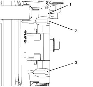
jury or death. Do not connect any electrical equip-
Illustration 26
g01131276
ment or disconnect any electrical equipment in an
explosive atmosphere.
Diagram for the installation of a connector plug (typical example)
(1) Electronic Control Module (ECM) connector
(2) Correctly inserted plug
(3) Incorrectly inserted plug
This document has been printed from SPI². Not for Resale
![]()
![]()
![]() KENR6224
KENR6224
91
Troubleshooting Section
|
|
of the plugs are missing, replace the plug. Ensure
that the plugs are inserted correctly into the
connector. Refer to Illustration 26.
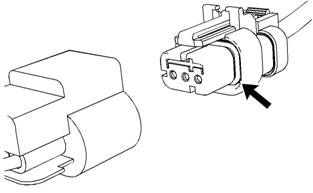
Illustration 27
Seal for a three-pin connector (typical example)
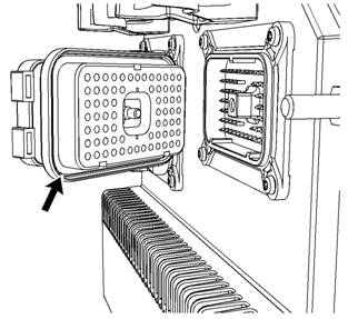
Illustration 28
Seal for ECM connec tor (typical example)
C. Disconnect the suspect connector and inspect the
connector s eal. Ensure that the seals are in good
condition. If necessary, replace the connector.
D. Thoroughly inspect the connectors for evidence
of moisture entry.
Note: It is normal to see some minor seal abrasion
on connector seals. Minor seal abrasion will not allow
the entry of mois ture.
If moisture or corrosion is evident in the connector,
the source of the moisture entry must be found
and the source of the moisture entry must be
repaired. If the source of the moisture entry is not
repaired, the fault will recur. Simply drying the
connector will not fix the fault. Check the following
items for the possible moisture entry path:
• Missing seals
• Improperly installed seals
• Nicks in exposed insulation
• Improperly mated connectors
Moisture can also travel to a connector through
the inside of a wire. If moisture is found in a
connector, thoroughly check the connector’s
harness for damage. Also c heck other connectors
that share the harness for moisture.
Note: The ECM is a sealed unit. If moisture is found
in an ECM connector, the ECM is not the source of
the moisture. Do not replace the ECM.
Expected Result:
The harness wiring, connectors, and seals are in
good condition. There is no evidence of moisture in
the connectors.
Results:
• OK – The harness wiring, connectors, and seals
are in good condition. Proceed to Test Step 2.
• Not OK – A fault has been found in the harness
or the connectors .
Repair: Repair the connectors or the wiring, as
required. Ensure that all of the seals are properly
in place. Ensure that the connectors have been
reattached.
If corrosion is evident on the pins, sockets or the
connector, use only denatured alcohol to remove
the corrosion. Use a cotton swab or a soft brush
to remove the corrosion.
If moisture was found in the connectors, run the
engine for several minutes and check again for
mois ture. If moisture reappears, the moisture is
wicking into the c onnector. Even if the moisture
entry path is repaired, it may be necessary to
replace the wires.
Verify that the repair eliminates the fault.
STOP.
This document has been printed from SPI². Not for Resale
![]()
![]() 92
92
Troubleshooting Section
KENR6224
|
|
|
|
A. Carefully inspect each wire for signs of abrasion,
of nicks, and of cuts.
Inspect the wires for the following conditions:
• Expos ed insulation
• Rubbing of a wire against the engine
• Rubbing of a wire against a sharp point
B. Check all of the wiring harness fasteners in order
to verify that the harness is properly secured. Also
check all of the fasteners in order to verify that the
harness is not compressed. Pull bac k the harness
sleeves in order to check for a flattened portion
of wire. A fastener that has been overtightened
flattens the harness. This damages the wires that
are inside the harness.
Expected Result:
The wires are free of abrasion, of nicks, and of cuts
and the harness is properly clamped.
Results:
• OK – The harness is OK. Proceed to Test Step 3.
• Not OK – There is damage to the harness.
Repair: Repair the wires or replace the wires, as
required. Verify that the repair eliminates the fault.
STOP.
Terminals
A. Visually inspect each terminal in the connector.
Verify that the terminals are not damaged.
Verify that the terminals are properly aligned in
the connector and verify that the terminals are
properly located in the connector.
Expected Result:
The terminals are properly aligned and the terminals
appear undamaged.
Results:
4.
damaged.
|
|
|
|
terminals, as required.
Verify that the repair eliminates the fault.
STOP.
Wire Terminal Connection
Perform the 45 N (10 lb) pull tes t on each wire. Each
terminal and each connector should easily withstand
45 N (10 lb) of tension and each wire should remain in
the connector body. This test checks whether the wire
was properly crimped in the terminal and whether the
terminal was properly inserted into the connector.
Expected Result:
Each terminal and each connector easily withstands
45 N (10 lb) of pull and each wire remains in the
connector body.
Results:
Test Step 5.
or a terminal has been pulled from the connector.
Repair: Use the 2900A033 Crimp Tool to replace
the terminal. Replace damaged connectors, as
required. Verify that the repair eliminates the fault.
STOP.
Test Step 5. Check Individual Pin
Retention into the Socket
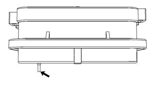
Illustration 29
Diagram for testing pin retention (typical example)
A. Verify that the sockets provide good retention for
the pins. Insert a new pin into each socket one
at a time in order to check for a good grip on the
pin by the socket.
This document has been printed from SPI². Not for Resale
![]()
![]()
![]()
![]() KENR6224
KENR6224
93
Troubleshooting Section
Expected Result:
The sockets provide good retention for the new pin.
Results:
• OK – The terminals are OK. Proceed to Test Step
6.
• Not OK – Terminals are damaged.
Repair: Use the 2900A033 Crimp Tool to replace
the damaged terminals. Verify that the repair
eliminates the fault.
STOP.
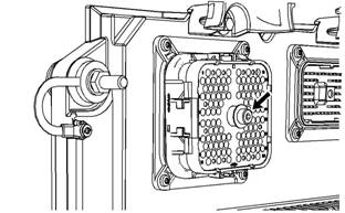
Illustration 30
g01132827
Test
Step 6.
Check the Locking
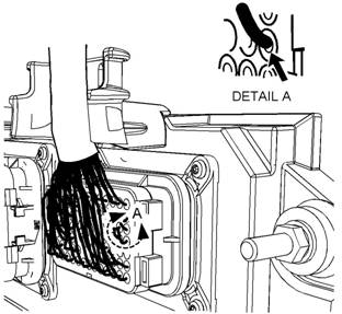
Allen head s crew for the 120 pin ECM connector (typical example)
a. Torque the allen head bolt for the 120 pin ECM
|
|
|
|
|
A. Ensure that the connectors lock properly. After
loc king the connectors, ensure that the two halves
cannot be pulled apart.
B. Verify that the latch tab of the connector is
properly latched. Also verify that the latch tab of
the c onnector returns to the locked position.
Expected Result:
The connector will securely lock. The connector and
the locking mechanism are without crac ks or breaks.
Results:
to Test Step 7.
connector is damaged or missing.
Repair: Repair the connector or replace the
connector, as required. Verify that the repair
eliminates the fault.
STOP.
on the Connectors
Visually inspect the allen head screws for the ECM
connectors. Ensure that the threads on each allen
head screw are not damaged.
A. Connect the ECM connectors.
|
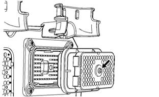
Illustration 31
Allen head screw for the 70 pin ECM connector (typical example)
b. Torque the allen head screw for the 70
pin ECM connector to 6.0 + 1.5 - 0.5 N·m
(55 + 13 - 4 lb in).
c.
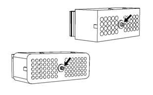
Illustration 32
g01133047
Allen head sc rew for the 40 pin customer connector and the 70 pin
customer connector (typical example)
B. Connect the customer connector.
This document has been printed from SPI². Not for Resale
